1. INTRODUCTION
Transcranial magnetic stimulation (TMS) is a non-invasive technique for studying human brain activity by generating a pulsed electric field in the brain. Simulating the exposure generates information concerning the exact location of stimulations, which is important during TMS.
Manufacturers have developed different kinds of TMS coils (Jalinous, 1998):
-
Simple coil: A circular winding
-
Figure-of-Eight-shaped coil: Similar to two simple coils (currents circulating in opposite ways)
-
Double cone coil: An 8-shaped coil with an angle between the two wings of the coil.
The common coil used for the TMS is Figure-of-Eight, first proposed by Ueno et al. (1988), where the field in the brain is generated with a Figure-of-Eight current loops placed above the head as in Wagner et al. (2004); Wagner et al. (2006); Yang et al. (2006). Rastogiet al. (2016) proposed a new quadruple butterfly coil to improved focality over the commercial Figure-of-Eight coil. This paper compares the magnetic and electric fields distributions on the human head during TMS using the well-known coil forms and the proposed novel one as well as shows the how deep brain excitation may these coils present. A heterogeneous female head, available commercially, is used to simulate the human head. Using FDTD-based software (SEMCAD-X ver. 14.4), magnetic field distribution on the head and brain tissues has been analyzed. Before TMS experiments on the head, the stimulation site could be found by this MRI-based head model simulation. To find the electric and magnetic field distribution on the head model due to the total exposure from the applied pulse signal, of 10000 A peak and 280 μs width, through the coil, the pulse signal is decomposed into Fourier series and run simulation at the different harmonic f1, f2, …, fn specifying the corresponding biological tissues parameters. The final results were extracted after combining the individual field at each harmonic. The well-known traditional coils, which are put on the patient’s head to stimulate the outer part of the brain, were working but overstimulated the surface when they tried to get deep brain stimulation. This was not only painful but also caused more effects on the outer part of the brain than they wanted and did little to stimulate the inside. In this paper, we examined two coil forms, i.e., Figure-of-Eight and the proposed Halo coil, for deep brain stimulation. The proposed coils showed a significant deep brain excitation as compared with well-known used coil, corresponding to the maximum field at the head surface.
2. NUMERICAL COMPUTATION
To achieve the TMS numerical computation, a quasi-static modeling is implemented to simulate the TMS coil over a human head. SEMCAD X that provides low frequency (LF) solver is used for the simulation. One of the quasi-static models that supported by SEMCAD X is the Magneto Quasi-Static (Biot-Savart) which is used in this paper to simulate the TMS models.
A heterogeneous high-resolution European female head (HR_EFH) model, available with Schmidt and Partner Engineering AG, is used. This MRI-based model consists of 121 different slices, with slice thicknesses of 1mm (ear region) and 3 mm and a transverse spatial resolution of 0.2 mm. Twenty Five different tissues are recognized and their electrical properties and densities are given according to material properties and densities database (IFAC, 2015). The HR-EFH model has been used by many authors for Radio Frequency and Microwave dosimetry, e.g., Al-Mously and Abousetta (2008-a) and Al-Mously and Abousetta (2008-b).
A Figure-of-Eight coil was designed numerically and simulated, using SEMCAD X, over the human head (HR_EFH).
The E field is only calculated in the lossy domain whereas the H field is calculated overall. Figure 1 shows the magnetic field distribution in the head model, only, due to Figure-of-Eight coil. Figure 2 shows the cross-sectional magnetic field distribution due to the same coil.
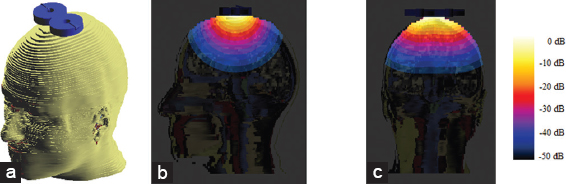
Figure 1. (a) Heterogeneous head model with Figure 8 coil, (b) The side cross-sectional distribution of the root mean square (RMS) modulus of the H vector field, (c) the back cross sectional distribution of the RMS modulus of the H vector field
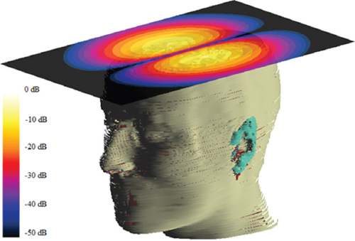
Figure 2. Vertical cross-sectional distribution of the root mean square modulus of the H vector field due to Figure 8 coil
To achieve deep brain stimulation, a novel Halo coil is suggested with the position shown in Figure 3. The diameter of the coil is chosen carefully so as to keep a minimum gap space of 1 mm with the human head, i.e., HR_EFH. The vertical position of the Halo coil can be adjusted based on the simulated brain part of interest. Figure 3 shows the magnetic field distribution in the head model, due to the halo coil.
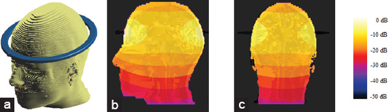
Figure 3. (a) Heterogeneous head model with Halo coil, (b) The side cross-sectional distribution of the root mean square (RMS) modulus of the H vector field and (b) the back cross-sectional distribution of the RMS modulus of the H vector field
It is obvious in Figures 1-3 that using the proposed Halo coil, the H field can reach to deep brain region with −10 dB of the maximum value at the surface, i.e., 0 dB. Halo coil may increase the H field by 30 dB, as compared with Figure-of-Eight coil, in the deep brain region. Accordingly, the Halo coil can be considered as a good candidate for a deep brain stimulation, without overstimulated the outer part of the brain.
3. CONCLUSION
This paper has presented a numerical computation using LF solver (SEMCAD X) to simulate a novel Halo coil that suggested for deep brain stimulation. The proposed Halo coil may avoid overstimulating the surface when they tried to get deep brain stimulation. This may not avoid patient’s pain only, but also to avoid any serious effect may be caused on the outer part of the brain.