1. INTRODUCTION
The Korre road is one of the important links between the Erbil city and tourism sites at the mountainous area within Erbil Governorate. Over this road, landslides pose a recurrent hazard to human life and livelihood. Landslide is the movement downslope of a mass of rock, debris, earth, or soil (soil being a mixture of earth and debris). Landslides occur when gravitational and other types of shear stresses within a slope exceed the shear strength (resistance to shearing) of the materials that form the slope. The hazard from landslides can be reduced by avoiding construction on steep slopes and existing landslides, or by stabilizing the slopes. Stability increases when groundwater is prevented from rising in the landslide mass by: (1) Covering the landslide with an impermeable membrane, (2) directing surface water away from the landslide, (3) draining groundwater away from the landslide, and (4) minimizing surface irrigation. Slope stability is also increased when a retaining structure and/or the weight of a soil/rock berm are placed at the toe of the landslide or when mass is removed from the top of the slope.
The methods that were adopted for the evaluation of slope stability against landslide hazards encompass the determination of geological strength index, introduced by Hoek (1994) and modified by Hoek et al. (1998); Hoek and Brown (1997), Hoek and Marinos (2007), and landslide possibility index (LPI) system suggested by Bejerman (1994). These two systems/indices are basically based on simple field observations of the rock mass. It is worth mentioning that we have adopted the latter method.
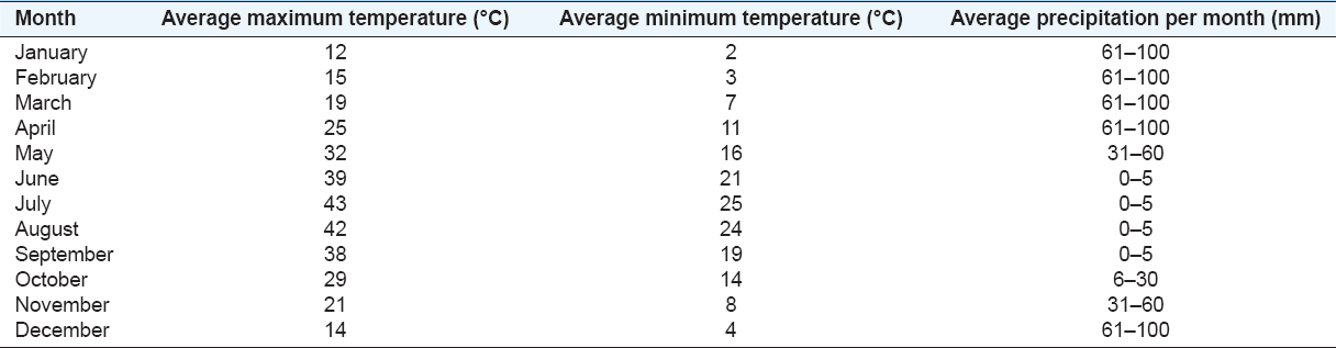
The study area represents a hilly area with a gradient of about 15%; however, the gradient of the road cut reaches 18%. The majority of the area is covered by clayey soil which is derived from the weathering of the underlying limestone beds of the Pila Spi Formation. The weather in the study area is semi-arid to wet with average precipitation of 61–10 mm in Autumn and Winter, and almost dry in many months [Table 1]. During December–April, very heavy rain showers often occur in the study area. Such heavy rain showers will increase the water content in the clayey soil; consequently, will increase the failure possibility due to high water pore pressure.
Table 1: Some climatic parameters in Erbil Governorate (http://www.whatstheweatherlike.org/iraq/erbil.htm)
Studies concerning the slope stability of the region did not exist; however, some relevant studies in other areas are mentioned below. Hamasour (1991) studied the unstable slopes (M.Sc. thesis) and presented the main unstable parts of the road. Jassim et al. (2013) studied the unstable slopes and considered the landslides and rock falls are the main mass movements’ phenomenon present in the study area. They presented their work through 14 studied stations and concluded that the possibility of sliding is high. Sidiq et al. (2016) studied a landslide that had happened on November 11, 2015 and documented the details and causes of the landslides; they also gave recommendations for stabilizing the concerned area. Jassim and Tokmachy (2015) studied the rock Mass Units of the Abandoned Koya Tunnel and recorded different geotechnical properties. Ibrahim (2017) reported about the unstable slopes along the road crossing. She conducted 18 studied stations and gave proposals to keep the road cuts stable.
The aim of this research work is to indicate the reason for the happened slope failure in the road cut and to recommend relevant methods for stabilizing the unstable slope.
2. MATERIALS AND METHODS
Site investigations were carried out on exposures along the main road connecting Permam to Shaqlawa town. The study area was described at three stations [Figure 1] with reference to the geological setting and slope characteristics. The elements of field investigation were topographic and geologic maps of different scales besides satellite images. In addition, five soil samples were obtained from the depth of 0.5 m for performing some selected geotechnical properties such as particle size distribution and indices properties. The stability of the slope at each station was investigated using LPI (Bejerman, 1994; 1998). The determination of LPI was based on 10 characteristic features derived from geological, structural, hydrological, and geomorphologic conditions of the given area. Estimated values of 10 parameters are added to determine the LPI. The degree of the hazard of the slopes was determined based on the obtained values of the LPI.
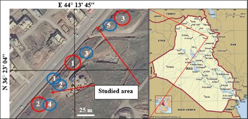
Figure 1. Zoom earth image of the studied area showing the three studied stations for landslide possibility index (encircled in red) and the location of soil samples (encircled in blue)
For slope measurements, we have used the Brinton compass, and those for discontinuities, we have used normal measuring tape. The soil samples were tested in Salahaddin University, College of Engineering.
2.1. Geological Setting
The geological setting of the studied area is shortly briefed; using the best available data. The geological setting includes geomorphology, tectonics, and structural geology, and stratigraphy.
2.2. Geomorphology
The studied area represents an erosional slope with a slope of 12°, formed due to the presence of many valleys draining the slope area [Figure 2]. The valleys flow from SE to NW, some of them flow over the barren, exposed rocks of the Pila Spi Formation; whereas others flow within the clastics of the Fatha formation and the covered thick residual soil. The latter facilitates infiltration of the rainwater; consequently, increasing the pore pressure. Apart from the existing studied slope failure, no such event was recorded in the studied area and near surroundings.
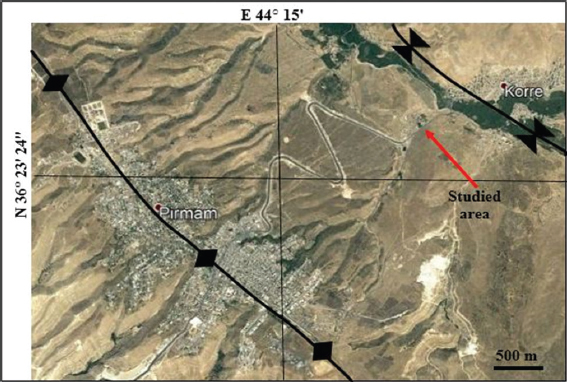
Figure 2. Satellite image of the study area and surrounding. Note the hilly terrain of the study area and the presence of Permam anticline and neighboring syncline
2.3. Tectonics and Structural Geology
The studied area is located in the High Folded Zone of the Outer Platform within the Arabian Plate; it also belongs to the Zagros Thrust–Fold Belt (Fouad, 2012). Permam anticline is NW–SE trending symmetrical anticline. Toward north is a syncline between Permam and Safeen anticlines. In the trough of the SE-ward plunging syncline, the studied area is located [Figure 2].
2.4. Stratigraphy
The exposed formation in the studied area is the Fatha Formation (Sissakian, 1979 Sissakian and Fouad, 2012) [Figure 3]. The Fatha Formation in the study area consists of thick reddish brown and soft claystone with very thin limestone and gypsum beds in cyclic nature. The thickness of the formation is about 130 m. The Fatha Formation is underlain unconformably by the Pila Spi Formation; it consists of well-bedded dolomitic limestone, dolostone, and rare marl (Sissakian and Al-Jiburi, 2014).
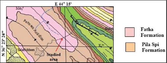
Figure 3. Geological map of the studied area and surroundings, only the concerned geological formations are shown in the legend (After Sissakian and Fouad, 2014)
2.5. Characters of the Unstable Slope
The studied area represents a road cut along the main paved road between Salahaddin and Shaqlawa towns. The length of the unstable slope is 180 m. The height difference between the road level and the highest unstable part of the slope is 30 m. The slide type is of soil sliding accompanied with a flow that had overflown on the constructed retaining wall [Figure 4 a, b and d]. The main slid mass is in the central part of the unstable slope with a scarp of 1.5 m [Figure 4c], length of 12.40 m and slope of 12°, with many crescent-shaped cracks in the, slid mass [Figure 4f].
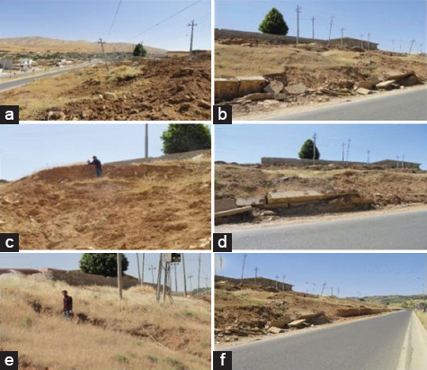
Figure 4. (a) Side view (looking northwards), (b) side view (looking northwards), (c) the develop scarp in the crown area, (d) the destroyed retaining wall, (e) longitudinal cracks, (f) crescent-shaped cracks developed in the slid mass
2.6. LPI
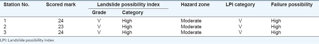
To check the stability of the studied area, we applied the Bejerman (1994) Method, which can be applied on both natural slopes and road cuts. We have used the special form for the three studied locations [Figure 1]: One in the unstable part of the slope and two others on both sides of the unstable slope, within stable parts. The raw field data are presented in Table 2 with the scored results of the LPI. By applying the total scored marks [Table 2] at each of the three studied stations, the category of LPI was obtained; following the given classification [Table 3] by Bejerman (1994 and 1998). The results are shown in Table 4. The LPI allows assessing the landslide possibility for rock slopes cut in mountainous roads (Bejerman, 1994), as well in natural slopes, as we have applied. The estimated values for each of the three studied stations [Table 2] are compared with the failure possibility classification (Bejerman, 1994; 1998), which consists of six classes; as shown in Table 3. Accordingly, the failure possibility is indicated at each of the four studied stations. The results are shown in Table 4.
Table 2. Raw field data for the three studied stations and their scored marks according to Bejerman (1994)
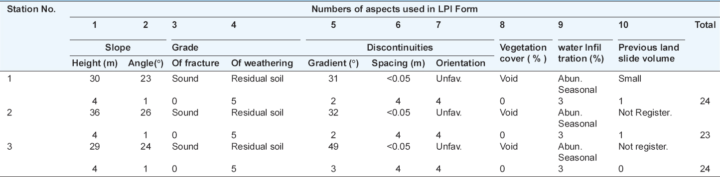
Table 3. Landslides hazard categories (After Bejerman, 1994; 1998)
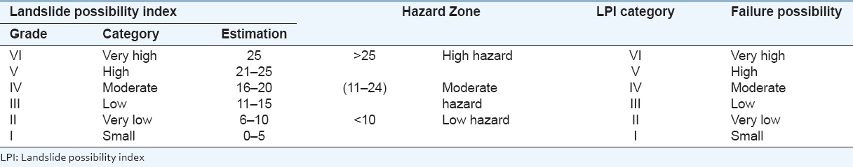
Table 4. LPI scored marks and hazard zones at the three studied stations
2.7. Laboratory Work
To indicate the type of the soil in the studied area, five samples were collected from different locations [Figure 1]. The collected samples were subjected to geotechnical tests. The details are mentioned hereinafter.
2.8. Geotechnical Tests
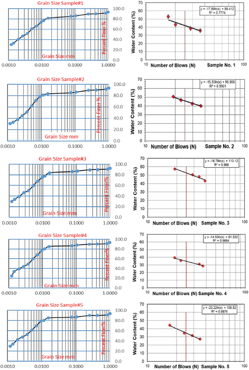
The five collected disturbed samples were subjected to grain size analysis and Atterberg limits test. Both tests were run following ASTM Nos. D 422 and D 4318, respectively. The results of the tests are presented in Table 5. The cumulative curves of the grain size analyze and those of the Atterberg limits are shown in Figure 5. According to the Unified Soil Classification System (USCS), the five samples are classified as low plasticity clay “CL.” By imposing the acquired geotechnical data [Table 5 and Figure 5] on the USCS chart, we have found that the soil type in the studied area is of the CL type. It means lean clay with low plasticity index, which will not behave as plastic when loaded and unloaded again.
Table 5. The results of Grain Size analysis and Atterberg Limits of the studied sample
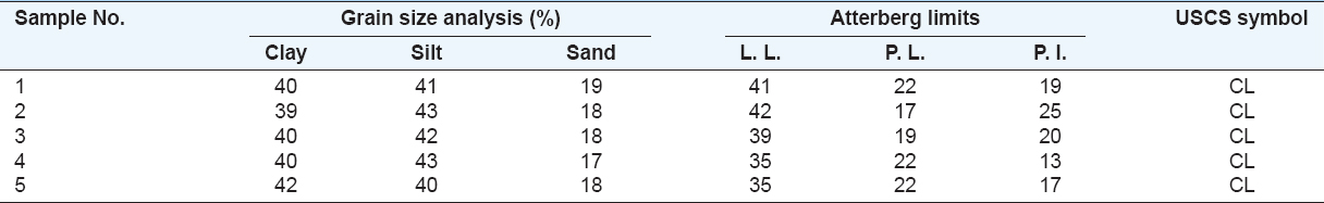
Figure 5. Geotechnical data of the studied samples (Left) Cumulative grain size curves and (Right) Atterberg curves
2.9. Geochemical Data
To indicate the clay minerals in the collected soil samples, we used the acquired data by Mirza and Faraj (2017) from applying the XRD test on the claystone of the Fatha Formation. They did not find any dominant clay mineral in the tested samples; therefore, none of them will have a significant effect on the soil; as the clay mineralogy is considered. The found main clay minerals of the tested samples are chlorite, smectite, mixed layer illite, and kaolinite. Accordingly, we considered the mentioned types of clay minerals to be the same in the soil without any significant importance as the stability of the road cut is concerned.
3. RESULTS
A slope along a road cut covered by residual clayey - silty soil originated from the weathering of the clastic rocks of the Fatha Formation at the northeastern limb of Permam anticline suffers from slope instability. A landslide had occurred; most probably of the rotational type associated with mudflow, which had over toppled and damaged the retaining wall [Figure 4b, d, and f]. We have thoroughly inspected the slope to indicate the reasons for the landslide; moreover, we collected five soil samples and subjected to the geotechnical test. We have found that the main reasons for the landslide are:
3.1. Oversaturation of the Soil
The clayey soil (lean clay) is oversaturated after heavy rain showers. The presence of limestone quarries [Figure 6a] in the upper part of the slope, facilitate the infiltration of the rainwater into the clayey soil, which is of CL type clay [Table 5] that contain 39 – 42 % clay, 40–43% silt, and 17 – 19 % sand. The Plasticity Index values range from 13 to 25. As the water saturation increases, the pore water pressure increases; consequently, the internal friction angle decreases (Terzaghi et al., 1996) and the slope fails.
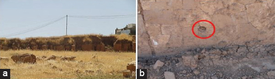
Figure 6. (a) Small rock quarry in the upper part of the failed slope, it facilitates the infiltration of the rainwater in the soil; consequently, accelerates the failure and (b) A blocked draining pipe
3.2. Bad Drainage System
To decrease the pore water pressure in the soil, a good drainage system should be adopted, especially in the retaining walls (Terzaghi, 1934; Ambrose, 1991; and FAO, 2017). The installed draining pipes in the retaining wall were not sufficient and were not designed properly; therefore, they were blocked by washed fine-grained soil [Figure 6b].
3.3. Improper Retaining Wall
The designed retaining wall is improper; as the height, construction materials, and thickness are concerned [Figures 7a, b and 8a]. The height of the wall is <½ of the slope height [Figure 7b]. Therefore, the wall could not resist the pressure exerted by the sliding of the clayey soil; accordingly, it was collapsed down and damaged, and locally, over toppled [Figure 7a and 8a]. To the left side of the main slid mass [Figure 7b], the retaining wall is already pushed off; it will collapse down in the next rainy season, if not proper precautions are considered in the reconstruction of the damaged retaining wall.
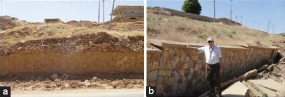
Figurer 7. (a) Toppled soil over the retaining wall, note the poorly designed drainage system in the retaining wall, almost no draining pipes are installed and (b) Note the height of the retaining wall (About 1.65 m) and compare it with the height of the slope
3.4. Overweighting the Slope
The local people have used large limestone blocks (LB) in their houses for leveling purposes. The size of the blocks ranges between 0. 25 and 0.5 m3, which means the weight of each block range between 0.625 and 1.25 tons per block. At least, 40 blocks are used in one single house [Figure 8b]; it means about 37 tons. The used rock blocks are within the effective zone of the slope because the slope is about 24○ and the height of the retaining wall is 1.5 m [Figures 7 and 8a]; therefore, the exerted weight of the LB [Figure 8b] will be within the effective zone. Accordingly, the weight of the LB have caused overweighting of the slope, which facilitates the soil failure; such cases are well explained by Terzaghi (1943).
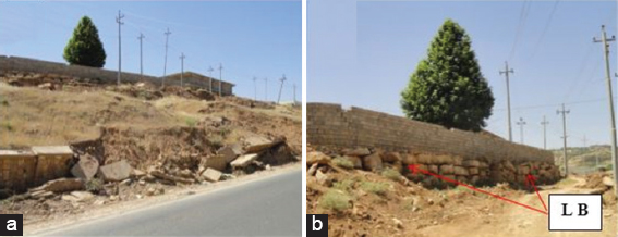
Figure 8. (a) The damaged retaining wall, note the height, thickness and used construction materials; all are improper, (b) Large limestone blocks used in the leveling of the ground below the house; consequently, causing overweight of the slope and its failure
4. DISCUSSION AND RECOMMENDATIONS
The main reasons for the slope failure in the studied area are discussed hereinafter, and relevant recommendations are given.
4.1. Drainage, Retaining Wall, and Oversaturation of the Clayey Soil
The road cut slope is covered by a clayey soil [Table 5]. To avoid oversaturation of the soil, which increases the pore water pressure and decreases the internal friction angle (Terzaghi, 1934; 1945; and Terzaghi et al. 1996), the following should be performed:
-
a. Preventing of quarrying LB from the existing small quarries in the upper part of the slope [Figure 6a].
-
b. Construction of many ditches from the uppermost part of the slope downward to the road and lining the ditches with relevant impervious material to reduce infiltration of the rainwater in the soil. The already existing vertical erosional rills [Figure 9a] can be used as draining ditches; after being lined with impervious relevant material.
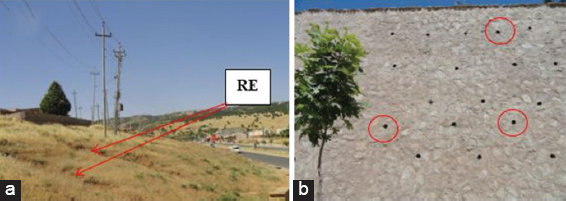
Figure 9. (a) Erosional rills along the slope, they can be lined with impervious material and used as draining ditches and (b) a retaining wall in the opposite side of the concerned landslide, note the excellent system of draining outlets (Some are encircled by red color)
-
c. Construction of a relevant retaining wall, with acceptable height and width, using reinforced concrete.
-
d. Providing the retaining wall with proper draining pipes to avoid oversaturation of the soil behind the wall. On the opposite side of the landslide, a proper retaining wall is constructed with the excellent draining system. The slope is higher than the failed slope, but is still stable [Figure 9b].
4.2. Over Weighting of the Slope, Slope Modification, and Reinforcement
The used LB in the leveling of the houses [Figure 8] has increased the applied external stresses over the slope. To reduce the applied stress and increase the shear strength of soil, which will stabilize the slope, the following should be performed.
4.3. Excavation of Undesired Materials
It creates a reduction in soil weight and can be accomplished by (i) removal of the soil mass at the top of the potential slide, (ii) flattening of the cut slopes above the road, and (iii) benching of cut slopes. Unfortunately, the excavated materials from the toe area were dumped on the slope. This also has increased the weight of the slope [Figure 10] and damaged the natural drainage.
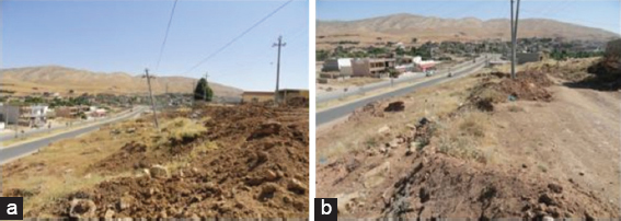
Figure 10. (a and b) The excavated materials from the toe are dumped on the already failed slope, this will increase the weight of the soil on the slope and damage the natural drainage. Accordingly, will increase the shear stress
4.4. Excavation and Filling Techniques
This should include: (1) Excavating the toe area of the landslide [Figure 11], (2) removing and replacing failed materials with lighter and more stable materials, or re-compacted debris, and (3) excavating to unload upper portions of a mass failure, and filling to load the lower portions of a mass failure.
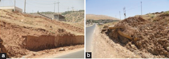
Figure 11. The toe area of the landslide is not cleaned properly. Parts of the damaged retaining wall are mixed with the slid mass, and the road’s draining ditch is destroyed and dumped
4.5. Preventing Overweighting the Failed Slope
Using large LB [Figure 8b and 12 a] in the construction of houses on the slope should be prevented as well as using heavy fences and benches that will overweight the slope. Moreover, the haphazardly constructed houses and unpaved roads [Figure 12b] should also be re-planned; the unpaved roads should be paved with proper draining ditches, to prevent infiltration of the rainwater in the soil.
Figure 12. (a) A heavily constructed house on the slope and (b) haphazardly constructed houses and unpaved roads. This will increase the infiltration of the rainwater in the soil and will increase the failure possibility
5. CONCLUSIONS
A slope along the road cut between Salahaddin and Shaqlawa towns suffers from instability, and the road cut was failed and blocked the road. Since the details of the failed slope damage during the removal of the failed materials; therefore, it is difficult to recognize the type of the failure. However, most probably it is of rotational type. The slope is covered by residual clayey - silty soil of CL type, which is lean clay with low plasticity index. The results of the LPI showed that the failure possibility of the road cut is high.
The whole slope will fail, and the nearby constructed houses most probably will be affected too, because they are within the effective zone of the failed slope if the slope is not treated relevantly.
6. ACKNOWLEDGMENT
This research work is performed under the umbrella of the University of Kurdistan Hewler; therefore, we would like to express our thanks to the authorities who approved the research work and facilitated the performance of the work. Thanks are also extended to Dr.Sirwan K. Mala (the Head of the Civil Engineering Department in Salahaddin University) to access their equipment and facilities, without those permissions, we could not perform the laboratory work, and the results of the current research would not be accurate.
REFERENCES
Ambrose, J. (1991). Simplified Design of Masonry Structures. New York: John Wiley and Sons, Inc. p. 70-75.
ASTM D-2487. (2000). ASTM Standard D2487, 2000, Standard Practice for Classification of Soils for Engineering Purposes (Unified Soil Classification System). West Conshohocken, PA: ASTM International.
Bejerman, N. J. (1994). Landslide Possibility Index System. Vol. 3. Rotterdam: Proceedings 7th International Congress of IAEG, Balkema. p. 1303-1306.
Bejerman, N. J. (1998). Evaluation of Landslide Susceptibility Along a Sector of State Road E-55, Cordoba-Argentina. Vol. 2. Vancouver, Canada, Rotterdam: Proceedings, 8th International Congress of IAEG, Balkema. p. 1175-1178.
FAO. (2017). Water Management Field Manual, Chapter 5: Surface and Slope Protective Measures. Available from: http://www.fao.org/docrep/006/t0099e/T0099e05.htm. [Last accessed 2018 Nov].
Fouad, S. F. (2012). Tectonic Map of Iraq, Scale 1:1000000. 3rd ed. Baghdad, Iraq: Iraq Geological Survey Publications.
Hamasur, G. A. (1991). Engineering-Geological Study of Rock Slope Stability in Haibat Sultan Area, NE Iraq. Erbil, Iraq: Un Publication. M.Sc. Thesis, University of Salahaddin. p. 153.
Jassim, H. M., Saad, S. A. & Ghafour, B. D. (2013). Slope Stability Assessment Along the Haibat Sultan Main Road, Koya, Kurdistan. Koya: Proceedings of First International Symposium on Urban Development.
Hoek, E. & Brown, E. T. (1997). Underground Excavations in Rock. London: Institution of Mining and Metallurgy.
Hoek, E. & Marinos, P. (2007). A Brief History of the Development of the Hiek-Brown Failure Criterion. London: Soils and Rock Mechanics.
Hoek, E., Marinos, P. & Benissi, K. (1998). Applicability of the geological strength index (GSI) classification for weak and sheared rock masses: The case of Athens schist formation. Bulletin of Engineering Geology and Environment, 57(2), 252-260.
Ibrahim, Z. J. (2017). Slope Stability at Haibat Sultan Road, Kurdistan Region, Iraq. Hewler: Final Graduation Project, University of Kurdistan. p. 46.
Jassim, H. M. & Tokmachy, A. A. M. (2015). Chracterization of rock mass units along the abandoned haibat sultan tunnel, Koya city, NE Iraq. International Journal of Engineering Technology, Management and Applied Sciences, 5(8), 158-176.
Mirza, T. A. & Faraj, R. O. (2017). Mineralogical and industrial assessment of clay from parts of the folded zone in Kurdistan region for ceramic production. Iraqi Bulletin of Geology and Mining, 13(1), 79-97.
Sidiq, S. A., Muhmed, A. S., Haris, G. K., Hamma, D. M., Abdullah, M. M., Bibani, H. H., Muhealldin, H. K., Mustafa, H. A., Sissakian, V. K. & Al-Ansari, N. (2016). Mechanism of haibat sultan mountain landslide in Koya, North Iraq. Engineering, 8, 535-544.
Sissakian, V. K. & Al-Jiburi, B. S. (2014). Stratigraphy. In: The geology of the high folded zone. Iraqi: Iraqi Bulleting of Geology and Mining, Special Issue No 6. p. 73-161.
Sissakian, V. K. & Fouad, S. F. (2012). Geological Map of Iraq, Scale 1: 10000000. 4th ed. Baghdad, Iraq: Iraq Geological Survey Publications.
Sissakian, V. K. & Fouad, S. F. (2014). Geological Map of Erbil and Mahabad Quadrangles, Scale 1: 2500000. 2nd ed. Baghdad, Iraq: Iraq Geological Survey Publications.
Sissakian, V. K. (1979). Report on Regional Geological Mapping of Erbil-Shaqlawa-Koi Sanjaq-Raidar Area. Iraq Geological Survey Library Report No. 975. p. 114.
Terzaghi, K. (1934). Large Retaining Wall Tests. Engineering News Record Feb. 1, March 8.
Terzaghi, K. (1943). Theoretical Soil Mechanics. New York: John Wiley and Sons.
Terzaghi, K., Peck, R. B. & Mesri, G. (1996). Soil Mechanics in Engineering Practice. New York: John Wiley and Sons.
Org (What’s the Weather like), 2018. Climate Data and Weather info for Every Country in the World. Available from: http://www. whatstheweatherlike.org/iraq/erbil.htm. [Last accessed 2018 Nov]