1. INTRODUCTION
In February 24, 2012, four landslides occurred along Dukan touristic road, which is also known; locally as Jwgmagh road, in the northeast of Dukan town, the Kurdistan Region, Iraq. In this study, they are called as Dukan landslides No. 1, 2, 3, and 4. The landslides were occurred after a road cut during 2008 which had left to the formation of steep road cuts slope along Dukan–Surdash road. One side of the main road was blocked by the slid mass for a long time until they constructed a new road, recently.
This study deals with the details and aspects of the landslides that are considered as geological hazards and the factors that caused the landslide. It also discusses the reasons of the sliding and the procedures for preventing such events and not to be happening again in the area.
The studied area is located in the east of Dukan Dam, along the southeastern limits of Dukan Reservoir, along Dukan–Surdash road, northwest of Sulaimaniyah city about 60 Km, northeast of the Kurdistan Region, Iraq. Geologically, it is located within the Kometan Formation along the plunge of Khalikan anticline toward Kalo anticline (Figures 1 and 2).
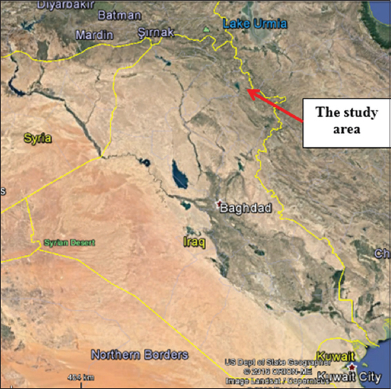
Figure 1. Google Earth image showing the study area

Figure 2. Flash Earth image showing Khalikan and Kalo anticlines and in between them the long and narrow syncline. Note the developed flat irons (FI) and Hogbags (HB)
In general, very few studies have been conducted in the Kurdistan Region and more especially in the concerned area, which deals with the slope stability assessments. Some regional studies, however, are available for similar events. Here are some of the studies:
Hamasur (1991) studied the unstable slopes (M.Sc. thesis) in Haibat Sultan Mountain and presented the main unstable parts of the road. Sissakian and Ibrahim (2002) conducted a geological hazard study of the whole Iraqi territory and considered the area under study as active mass movement zone. Sissakian and Ibrahim (2005a) compiled the Geological Hazards Map of Iraq and considered the area around Dukan Reservoir as Unstable Mass Movements Zone. Sissakian and Ibrahim (2007) compiled the Geological Hazards Map of Kirkuk Quadrangle at a scale of 1:250,000 and presented the landslide area on the map as unstable area. Hamed et al. (2013) studied the unstable slopes in the road crossing Haibat Sultan Mountain and considered that the landslides and rock falls are the main mass movements’ phenomenon present in the area. Sidiq et al. (2016) studied a landslide that had happened on 11//11/2015 at Haibat Sultan Mountain road crossing and documented the details and causes of the landslides; they also gave recommendations for stabilizing the concerned area.
The studied area is located in the east of Dukan Dam, along the southeastern limits of Dukan Reservoir, along Dukan–Surdash road, northwest of Sulaimaniyah city about 60 Km, northeast of the Kurdistan Region, Iraq. Geologically, it is located within the Kometan Formation along the plunge of Khalikan anticline toward Kalo anticline (Figures 1 and 2).
In this study, we have used the following materials:
-
Topographic and geological maps of different scales.
-
Google Earth and FLASH Earth images.
-
Different geological published articles and reports.
-
We have conducted a fieldwork in March 11 and May 20, 2017, to study the details of the landslides and conduct significant measurements, besides documentary field photos.
Using the available topographical and geological maps of different scales with the help of FLASH Earth and Google Earth images, the locations of Dukan Landslides are determined and the stability of the area and near surroundings is evaluated. The parameters of the landslide were measured during the fieldwork, which was carried out on March 11, and May 27, 2017. The exact limits of the landslide were mapped, and significant parameters of the landslide are measured; such as crown area, shear plane, dimensions of the landslides, dip, and strike measurements of bedding planes and joint planes are also measured and represented on the Schmidt net using software Stereonet 9; moreover, the different parts of the landslides are documented by tens of field photos. Moreover, we applied landslide possibility index method (Bejerman, 1994) in each of the four landslides. We also used drones to make photography from high areas, which gave us an excellent top view for the studied landslides.
2. GEOLOGICAL SETTING
The geology of the studied area, including geomorphology, tectonics and structural geology, and stratigraphy is given briefly; hereinafter, it is explained by Sissakian and Fouad (2012; 2014a and b; Sissakian and Al-Jiburi, 2014). The geological map of the studied area and near surroundings is presented in Figure 3.
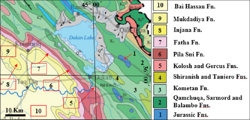
Figure 3. Geological map of the studied area and near surrounding (After Sissakian and Fouad, 2012)
1.1. Geomorphology
The main landform developed in the studied area is the rounded shaped mountains and hillocks, which are developed due to the prevailing of fairly hard to hard marly limestone of the Kometan Formation. Flatirons and hogbacks (Figure 2) are also developed in the east of the studied area within the Shiranish Formation. Some of the valleys are very narrow and deep exhibiting very clear active gulley erosion (AGE) indications (Figure 4).
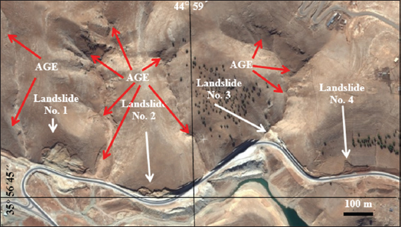
Figure 4. Flash Earth image (facing south) showing the four existing landslides. Note the rounded-shaped mountains and hillocks. Active gulley erosion (AGE) indications
1.2. Tectonics and Structural Geology
The studied area is located within the high folded zone of the outer platform, and it belongs to Arabian Plate (Fouad, 2012). The zone is part of the Zagros Fold–Thrust Belt. The studied area is located along the northeastern part of the NW plunge of Khalikan anticline, toward the axis of a narrow syncline between Khalikan and Kalo anticlines (Figure 2). The dip amount of the bedding planes ranges from 12 to 70 with two sets of joints, almost with perpendicular planes.
1.3. Stratigraphy
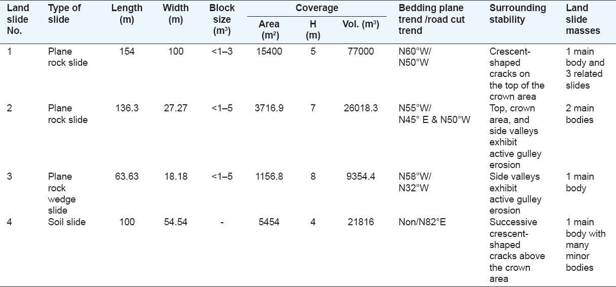
The studied area is within the Kometan Formation, which is overlain by the Shiranish Formation (Figure 3). The formation consists mainly of marly limestone, white, fairly hard to hard, jointed and well bedded. The thickness of the individual bed ranges from 15 to 45 cm. In some areas, the thickness reach to more than one meter. However, the lower part is massive with thick beddings that exceed 1 m (Figure 5). Some pyrite and chert nodules occur within the marly limestone as well stylolite is well developed. The thickness of the formation in the studied area is about 175 m.
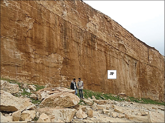
Figure 5. Massive bedding in the lower part and thin bedding in the upper part of the Kometan Formation. Note a master joint plane (JP) in Landslide No. 3, forming a vertical scarp (~8 m)
3. THE CHARACTERISTICS OF DUKAN LANDSLIDES
The existing four landslides in the studied area are checked and mapped in the field. Three of them (Landslides Nos. 1, 2, and 3) are within the rocks of the Kometan Formation, whereas, the fourth one (Landslide No. 4) is within the residual soil, which covers the exposures of the Kometan Formation (Figure 4). The characteristics of the landslides are measured, recorded, and described, including dimensions, size of the slid blocks, dip and strike of the bedding and joint planes, and other significant aspects such as stability of the surrounding area, the orientation of the slid mass, and number of the main parts within each slide. The characteristics of the four existing landslides are mentioned in Table 1.
Table 1. Characteristics of the studied four landslides
4. CAUSES OF THE LANDSLIDES
The main reason for the four landslides is the haphazard road cuts. However, besides the road cut, each landslide has its own reasons that have contributed in the sliding. Each landslide is discussed separately with indications for the causes as confirmed by different types of field photos and satellite images.
4.1. Landslide No. 1
This is the largest landslide within the studied area (Figures 4 and 6 and Table 1). The orientation of the road cut is N 50° W, with almost vertical cut (Figure 6/c), whereas the bedding plane strike is N 60° W with the dip amount of 12–48° NE. The intersection of the road cut and bedding strike (Figure 6/b-d) have developed unstable slope. Moreover, the abrupt change in the dip amount has developed a crushed flexure zone besides another crushed zone developed due to the intersection of the two joint sets: N 45° E/85° NW and N 45° W/70° NE. The crushed zones will facilitate water infiltration inside the limestone; consequently, this will increase the pore water pressure, and when it increases more than the internal friction angle, sliding will occur (Terzaghi, 1943; Terzaghi et al., 1996).
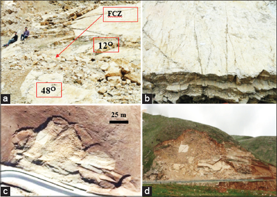
Figure 6. Landslide No. 1: (a) Note the abrupt change in dip amount forming a flexure crushed zone (FCZ), (b) intersection of two joint sets has formed another crushed zone. Both zones contributed in the development of the slide, (c) flash Earth image, note the vertical road cut is still visible in the toe area, and (d) general view of the landslide
4.2. Landslide No. 2
This landslide consists of two conjugate slides (Figures 4 and 7 and Table 1). The road cut is in two orientations, N 45° E and N 50° W, with almost vertical cut (Figure 7/c and d), whereas the bedding strike is N 55° W with a dip amount of 20° NE. The two sets of joints, N 45° E/80° NW and N 60° W/85° NE, which are almost parallel to both road cuts, interfere with the two road cuts’ orientations forming unstable slope (Figure 7). Moreover, the landslide area is surrounded from three directions by very AGE (Figure 4), which contributes and accelerates the sliding.
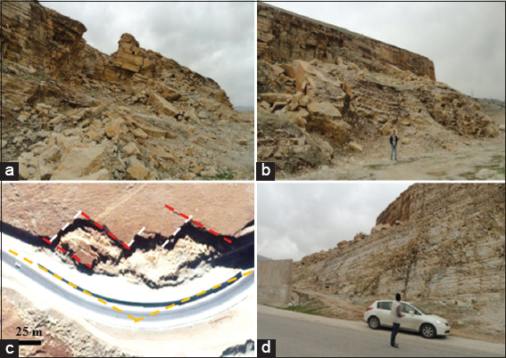
Figure 7. Landslide No.2. (a and b) Note the two developed joint sets and the slid masses, (c) flash earth image showing the relation between the joint trends (in red and white dashed lines) and directions of road cuts (in orange dashed lines), and (d) note the stable vertical road cut, which is higher than the failed road cut because the road cut direction does not interfere with the two main joint planes
4.3. Landslide No. 3
This landslide consists of one single wedge plane slide (Figures 2 and 8 and Table 1). The road cut is in the orientation of N 32° W, with almost vertical cut (Figure 8/c), whereas the bedding plane strike is N 58° W with a dip amount of 12° NE. The two sets of joints N 45° E/85° NW (Figure 8) and N 60° W/85° NE intersect each other and interfere with the road cut’s orientation forming one wedge plain slide (Figure 8/c and d). Moreover, the existing of narrow and steep valley left of the sliding (Figures 4 and 8/c) has contributed to the development and acceleration of the sliding. The two joint planes remained as vertical walls with heights of 5–9 m and are forming active rock fall areas (Figures 5 and 8).
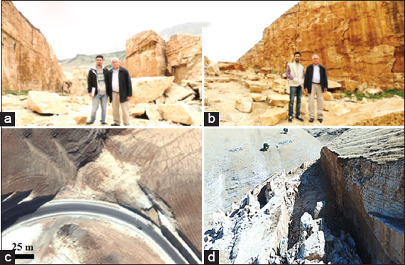
Figure 8. Landslide No. 3, (a) wedge plane sliding facing downslope, (b) wedge plane sliding facing upslope. In both photos, the authors are standing on the shear plane. Note the fallen blocks from both joint faces, which represent the limits of the slide. (c) Flash Earth image, note the stable road cuts (SRC) on both the sides of the landslide, although they are higher than the failed slope, those road cuts are stable because the trend of the road cut does not interfere with the joint planes, (d) top view; photographed by drone, the wedge shape sliding is clearer in this view
4.4. Landslide No. 4
This landslide is within the residual soil formed on the top of the exposed rocks of the Kometan Formation (Figures 4 and 9, and Table 1). The road cut is in in the orientation of N 82° E, with almost vertical cut (Figure 9/b and d). The main reason for the sliding is the water saturation that has increased the pore water pressure more than the internal friction angle; consequently, sliding had occurred (Terzaghi, 1943; Terzaghi et al., 1996). On both the sides of the landslide, there are two longitudinal depressions (LD) (Figure 9b and d) in which the soil is developed. Moreover, on the left side of the slide, the location of a high tension post (Figure 9c and d) has caused water accumulation and already a new small sliding is developed (Figure 9c). The two depressions and the high tension post location have accumulated the water and increased the water saturation of the soil and consequently have caused sliding, which is still active.
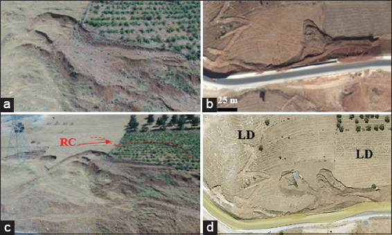
Figure 9. Slide No.4, (a and c) photos by drone; note the developed crescent-shaped cracks, (b) flash earth image, compare the size and shape of the sliding with those in a and c which is due to the difference in dates of the images. (d) Flash earth image, note the formed LD on both sides of the slide. Note the recently developed crack (RC) within the cultivated land in caption C, it was not yet developed at the scene of caption D
5. LANDSLIDE POSSIBILITY INDEX (LPI)
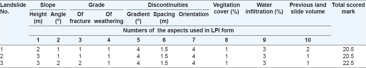
To estimate the LPI of the studied landslides (Nos. 1, 2, and 3), we have applied Bejerman (1994) Method, which can be applied on natural slopes as well as road cuts. We estimated the required 10 factors some directly from the field others from relevant satellite images. As Landslide No.4 is in soil, therefore, we could not apply LPI method. The raw field data are shown in Table 1I, whereas the given weights (Bejerman, 1994) to each factor are presented in Table 3. The original used form (Bejerman, 1994) is shown in Form (1).

Table 2. Raw field data of the four studied landslides (After Bejerman, 1994)
Table 3. The scored grades of the studied four landslides following Bejerman (1994) method
By applying the scored marks (Table 3) at each of the three landslides, the category of LPI (Table 4) is obtained (Table 5), following Bejerman (1994 and 1998).
Table 4. Landslides hazard categories (After Bejerman, 1994 and 1998)
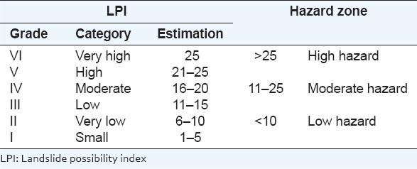
Table 5. LPI scored marks and hazard zones in the studied area
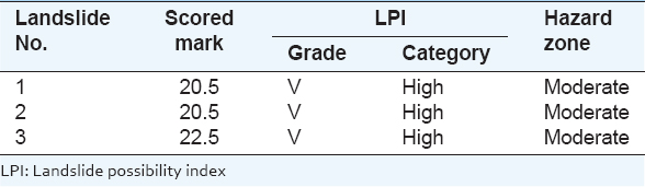
The estimated values for each of the three studied landslides (Table 3) are compared with the failure possibility classification (Bejerman, 1994), which consists of six classes (Table 6). Accordingly, the failure possibility is indicated on each of the three studied stations. The results are shown in Table 7.
Table 6. Failure category for each LPI category (after Bejerman, 1994)
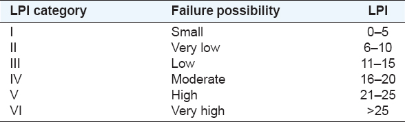
Table 7. Failure possibility estimation at each of the four studied stations

6. STEREONET PROJECTION
To indicate the relationship between the road cut trends and the status of the exposed rocks, we have used Stereonet 9 software in the construction of Schmidt net (Figure 10). The recorded data about the bedding and joint planes and road cut orientations in the first three landslides (Nos. 1, 2 and 3) are used in construction of the stereonets. We have assumed the internal friction angle to be 26○ because the rocks are marly limestone. Moreover, we have used Kulatilake et al. (1999) method to indicate the unstable parts at each landslide.
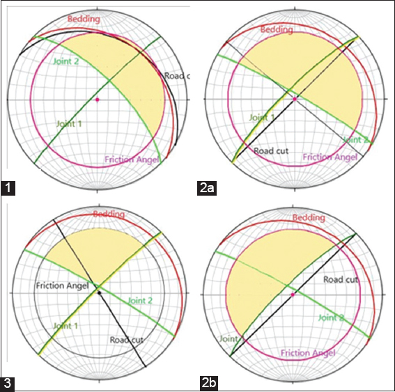
Figure 10. Four stereonet projections of the three landslides Nos. 1, 2, and 3 (2a and 2b are for two different road cuts). Bedding planes are in red, joint planes are in green, and road cuts are in black, whereas the internal friction angle is presented in violent color. The risky areas are colored by light beige color, which represents the critical unstable slopes that should be avoided, if a new road cut and/or stabilization work will be carried out on at the three landslide areas or any other road cut at the same vicinity
In Landslide No. 1, the unstable part is very large because the trends of the bedding plane and the road cut are almost the same. In Landslide No. 2, both roads are almost parallel to the main two joint trends (Figure 10, 2a and 2b); therefore, the unstable area is very large. In Landslide No. 3, large part is unstable because the two joint planes intersect in wide angle and the road cut trend is within the area of two joints intersection; therefore, a wedge slide had occurred. These data can be used to estimate the best trends of road cuts at each of the three landslides to have safe road cuts.
7. DISCUSSION
A road along the eastern bank of Dukan reservoir had many critical slopes (Figure 11 Top) showing indications for possible mass movements to take place in different parts. In 2012, the concerned part of the road suffered from slope failures in four main movements (Figure 11 Bottom) after executing of haphazard road cuts for widening purposes.
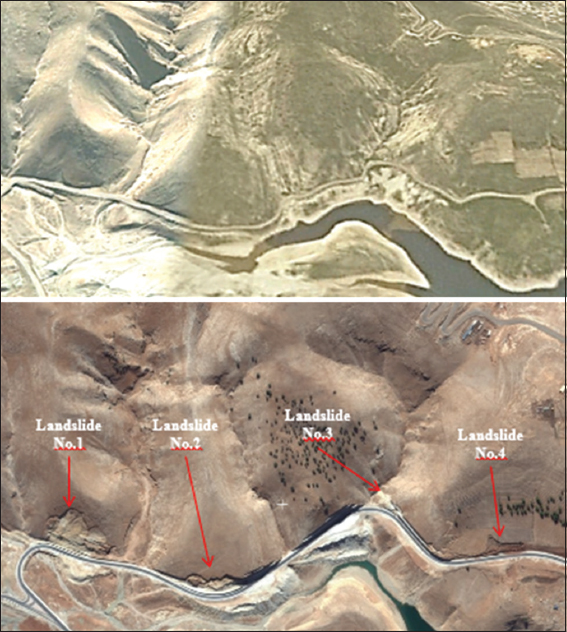
Figure 11. (Top) Google Earth image of the studied area facing south (during 2002); before the occurrence of the four main mass movements, (Bottom) Flash Earth image facing south (during 2017) showing the four main landslides
We studied the LPI of the three landslides (Table 5) and have estimated the failure possibilities (Table 7). The first three landslides (Nos. 1, 2, and 3) showed high possibility for possible refailure. This is attributed to the following aspects: (1) The intersection of the road cuts’ trends with the trends of the bedding planes and two sets of joint planes (Table 1, and Figures 4-8 and 10), (2) the presence of active erosion areas surrounding the landslide areas (Figure 4), and (3) the oscillation of the water level in Dukan reservoir has formed unstable slopes along the lowermost parts of the already existing landslides (Figure 12) and these in turn will effect on the toe area of the concerned slides. Such cases are well known and presented by many researchers, among them are Schuster (2006), Singh et al. (2012), and Kaczmarek et al. (2015). In Landslide No. 4, although no LPI was applied, it still shows indications for high possibility of sliding. This is attributed to the following aspects: (1) The thick residual soil on the rocks of the Kometan Formation (Figures 9 and 13) increases the rainwater infiltration, (2) the location of the high tension tower (Figure 13 Right) has played as increasing factor for the rainwater infiltration, and (3) the presence of the orchard field (Figure 13) has increased the infiltration of the rainwater. The recent cracks in the soil are up to 35 cm deep, with scarps’ heights up to 1.8 cm (Figure 13).

Figure 12. Top view photos (photographed by drone) showing indications of slope failure. (Left) Longitudinal crack (LC) along the road, (Right) crescent-shaped (CS) successive cracks
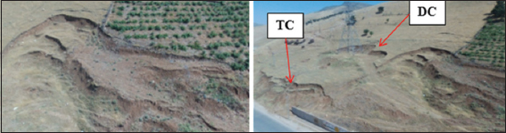
Figure 13. Top view photos (photographed by drone) showing landslide No.4. (Left) Note the developed crescent-shaped successive cracks, (Right) Note the developed cracks in the place of the high tension tower (DC) and those in the toe area (TC) along the road
In the first three landslides (Nos. 1, 2, and 3), clear indications were present at the same areas where the landslides already had occurred (Figure 14). However, the responsibility of the road cuts or those who were concerned with the maintenance of the road did not pay any attention to those indications and/or did not recognize them. Otherwise, the landslides would not be happened.
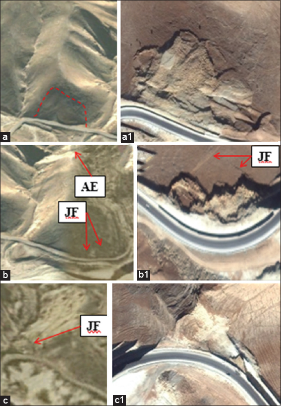
Figure 14. (a) Location of landslide No. 1, note the presence of the developed traces for the beginning of the slide, and the active erosion on both sides in valleys. (a1) Landslide No. 1, (b) Location of landslide No. 2, note the active erosion area on both sides along the valleys, as well in the uppermost part (AE), and the traces of fractures along joints (JF), (b1) Landslide No. 2 note the continuation of the joint as afracture (JF) on the surface. (c) Location of landslide No. 3, note the active erosion in the valley, and the trace of joint fracture (JF) in the location of the slide, (c1) note the stable slope along the road on both sides of the landslide
In landslide No. 4, it is not clear if there was any indication before the failure happened. Because the available satellite images are not clear (Figure 15a). A clear bulge, however, occurs along the road cut, which is most probably developed to a slope failure due to water saturation, consequently, increasing the water pore pressure and decreasing the internal friction angle (Terzaghi, 1943; Terzaghi et al., 1996). The single landslide (Figure 15b) is developed into a series of landslides effecting on the whole slope (Figure 15c and d), which is covered by residual soil. The crescent-shaped cracks (Figure 15c and d) are clear indication that the whole slope is not stable and new sliding will occur most probably next rainy season.
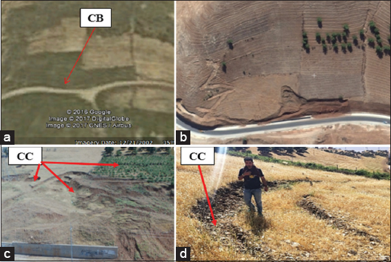
Figure 15. Landslide No. 4. (a) Google Earth image (2002), note the slope is still stable; however, a clear bulge (CB) can be seen along the road cut, (b) flash earth image, note the slid mass has partly covered the constructed retaining wall and the slopes on both sides of the slide are still stable, (c) drone photo (May, 2017), compare the size of the slide with that in (B), note the developed crack (CC) in the orchard field, and (d) drone photo (May, 2017), crescent-shaped cracks in the uppermost part of the slope, they are up to 0.35 m deep and up to 0.40 m wide. The crescent-shaped cracks are good indication that the slope is not stable and new slide will happen soon after being saturated by the rainwater
To maintain stabilization of the slopes along the road cuts, retaintion walls were constructed in the unstable slope areas (Figure 16). The constructed retention walls, however, were not relevantly designed and constructed (Figure 16a). Therefore, some of them are already destroyed because the walls cannot bear the weight of the slid masses and/or the slid mass overtopped the retention wall, as in the Landslide No. 4 (Figure 15b). Another attempt to maintain stabilization of the slopes is the construction of ditches in the toe area, as in Landslide No.3 (Figure 16c), regardless to the beginning of a slope failure in the lowermost part of the slope (Figures 12 and 16d). Such indications should be considered and corrective actions should be carried out; otherwise, all other attempts to keep stabilization of the slopes will result in vain.
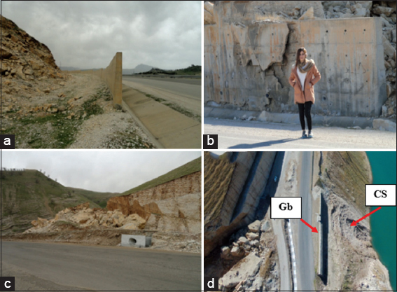
Figure 16. (a) A retaining wall in Landslide No. 2, not relevantly designed and constructed, (b) A destroyed retaining wall in Landslide No. 1, (c) maintenance in the toe area of Landslide No. 3, (d) drone photo (May, 2017) of Landslide No. 3, note the developed crescent-shaped cracks (CS) as indication for beginning of a slope failure below the landslide; regardless to the constructed gabions (Gb), which has increased the weight of the toe area; facilitating a new failure. Also note a vertical SRC, which is higher than the failed slope
From reviewing the road cut trends and their heights (Figure 17), it is very clear that one of the main reasons for the landslides is the trend of the road cuts, as shown in SRC of higher escarpments (Figure 17a and c), whereas, others with lower heights are not stable. Moreover, the failure had occurred in road cuts of certain trend (Figure 17b and c), and along both sides of the failed slope, the road cuts are stable as in Landslide No. 3 (Figure 17b) and Landslide No. 2 (Figure 17c). This is attributed to the interference of the road cut trend, and bedding and joint planes (Figure 10). Another reason that will facilitate slope failure is the overloading of the slopes (Figure 17d). The constructed gabion in the toe area of Landslide No. 3 will destabilize the slope, especially the lower part, which is in contact with the water in Dukan reservoir. Crescent-shaped cracks already started to be developed (Figure 16d) in the lowermost part of the slope indicating unstable slope that will fail soon.
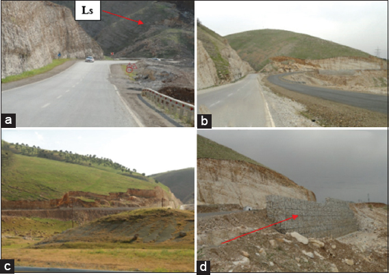
Figure 17. Landslide No. 3, (a) Note vertical stable road cut (SRC); left of the landslide (Ls), which was not yet fully developed, (b) note the stable vertical road cuts on both sides of the landslide and compare the size of the landslide with that in caption A, (c) Landslide No.2, also note the vertical SRC on both sides of the landslide, for the same reason, (d) A constructed gabion (Gb) in the toe area of Landslide No. 3, it will increase the possibility of failure, not to stabilize it; as thought by the responsible road engineers
7. CONCLUSIONS
Three of the four main landslides are developed at road cuts on the eastern bank of Dukan Dam reservoir which are within the well bedded and jointed marly limestone beds of the Kometan Formation, whereas the fourth one is developed within the residual soil, which partly covers the outcrops of the Kometan Formation. In the first three landslides, the intersection of the road cut trends with the trends of the bedding planes and planes of two joint sets is the main reason of the sliding. This is confirmed by the presence of higher road cuts that are still stable on both sides of the three landslides because the trends of the road cuts do not interfere with the bedding and joint planes. Nevertheless, the presence of very AGE in the surrounding valleys of the three landslides has accelerated and facilitated the sliding.
In Landslide No. 4, the main sliding reason is the oversaturation of the clayey residual soil by means of the presence of LD, the orchard field, and the undumped location of the high tension tower. All these aspects acted as increasing agents for water infiltration; consequently, increasing of the water pore pressure and decreasing the international friction angle have led to the slope failure.
8. RECOMMENDATIONS
Certain precautions should be considered to keep the stability of the road cuts before the next rainy season. These are: (1) To dig a ditch on the highest part of each landslide, line it with concrete or any other relevant synthetic impervious material to decrease water infiltration to the bedding planes, (2) to construct relevant retention wall with excellent drainage system in the front of each landslide, (3) to remove the slid masses from the landslide areas, as they form overweight on the top of the toe areas, and (4) to treat the toe area in Landslide No. 2 which is facing Dukan Dam reservoir by constructing an impervious diaphragm in front of the slope to decrease water infiltration in the toe area; otherwise the whole mass will slide down.
In Landslide No. 4, the following precautions should be considered: (1) The location of the high tension tower should be well dumped, (2) to dig a ditch between the orchard field and the landslide area and line it with concrete or a synthetic impervious material to decrease water infiltration to the soil, (3) to dump all present cracks in the upper parts of the landslide and the long one within the orchard field, (4) to construct relevant retention wall with excellent drainage system to avoid over saturation of the soil, and (5) to remove the slid masses in the toe areas and near surroundings of the landslide areas.