1. INTRODUCTION
The process of cutting transportation and proper hole cleaning is substantial in any drilling program. The success of any drilling operation is the result of efficient and proper cleaned hole. Hole cleaning is the capability of the drilling fluid to transport the cutting produced during drilling operations up to the surface and suspend the cuttings (Bourgoyne and Millhein, 1991). Many studies on hole cleaning have been carried out by different scientists and researchers over the past decades. The numbers of highly deviated and horizontal wells have increased significantly as a result of improved related knowledge and technology. Integration of optimum drilling fluid properties and implementation of best drilling practices are necessary for good hole cleaning. As a result, hydraulic simulation or experimental work of wellbore cleaning in drilling operation is highly recommended before drilling. For adequate hole cleaning, drilling fluid is expected to possess such rheological properties that can efficiently transport cuttings to surface (Akram and Maha, 2017). Cutting carrying index (CCI) which is a function of drilling fluid is used as simple tool to determine the efficiency of hole cleaning in drilling operations (Duan et al., 2010). Different mechanisms which control wellbore angles within different ranges define (a) wellbore configuration (depth, hole angle, hole size, or casing/wellbore inside diameter, and pipe size), (b) fluid properties (density and rheological properties), (c) cuttings characteristics (density, size, shape, bed porosity, and angle of repose), (d) pipe eccentricity and rotary speed, and (e) cuttings bed heights and annular cuttings concentrations as function of operating parameters (flow rate and penetration rate) (Duan et al., 2010). The efficiency in vertical and deviated wellbores has been reported to depend on some factors such as average fluid velocity, hole geometry and inclination, the size of cuttings and their shape, concentration of the cuttings, cuttings transport velocity, fluid flow regimes, drill pipe rotation, pipe eccentricity, fluid properties and rheology, rate of penetration, and multiphase flow effect. Any change in the angle of deviation of a well results in changing the lifting capacity of a drilling mud. As the angle of the inclination of well increases, the ability of drilling mud to lift the drill cuttings (Bourgoyne and Millhein, 1991). This happens due to the accumulation of the cuttings on lower side of the annulus and forming moving or stationary cutting beds instead of being carried out of the annulus. Therefore, the drilling mud requires more power to remove the cuttings in bended area of the well.
2. CALCULATION METHODS
The drilling formula sheet V16 is used for calculating most of the important factors. This sheet contains all the formulas needed for calculating the hydraulics, well control, and equipment data. This Drilling Formula Sheet is based on the book Applied Drilling Circulation Systems book by Ciuo and Liu (2011).
According to the mentioned sheet and book, the calculations are done in the following manner:
-
• For calculating critical flow rate according to the sheet, the following equations are used.
The effective viscosity equation for critical velocity is listed below:
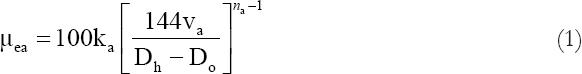
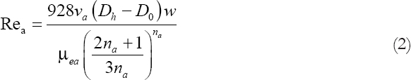
The Reynolds number equation for critical velocity is listed below:
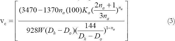
The critical annular velocity equation is listed below:
After we get the critical velocity, we can figure out the critical flow rate by the following equation:

-
• For calculating optimum flow rate according to the sheet,
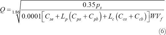
The equation is finding the optimum flow rate based on maximum hydraulic horsepower or maximum impact force using the following equations:

Solve for Q:
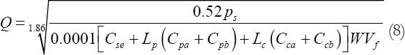
Optimum flow rate at maximum impact force:

Solve for Q:
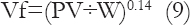
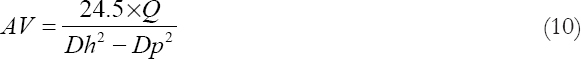
For calculating slip velocity according to the sheet, the following equations are used:
Determine annular velocity with the following equation:
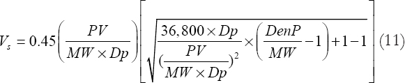
Determine cutting slip velocity with the following equation:
The CCI according to the formula sheet used is calculated by the following method:


-
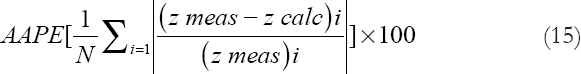
• For calculating the average absolute percentage error, the following equation is used:
3. DATA AND RESULTS
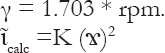
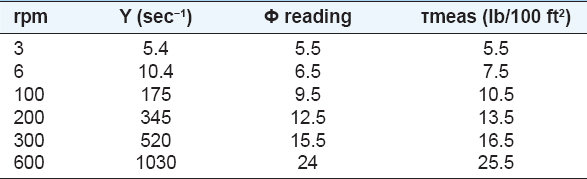
The Fann-VG readings are converted to shear stress (Ib/100 ft2) and the rpm values to shear rate in sec−1 using the relations (Rabia, 1998). Table 1 presents the dial readings at different RPM of the Fann-VG meter.
τmeas = 1.067 ϕ
Table 1. Drilling fluid prosperities

The results are shown in Table 2. Figure 1 is used to define which model our fluid obeys to choose the proper equations.
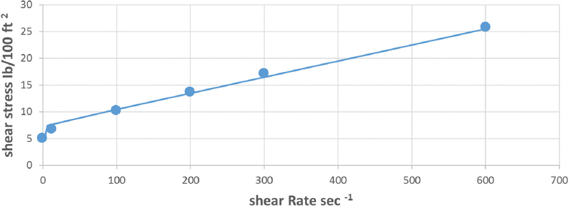
Figure 1. Shear rate and shear stress relationship
Table 2. Shear rate and shear stress values
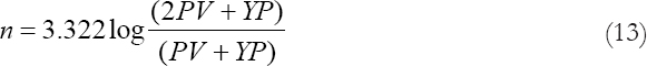
Values of n are calculated using equation 13 and values of K are calculated using equation 14.
Table 3 shows that the best non-Newtonian rheological model which fits the rheogram of the drilling fluid using equation (15) is 7.1% (Aswad, 1996) and is the power-law model with AAPE 6–8% while for Bingham plastic model.
Table 3. Functions which are required to perform AAPE calculation
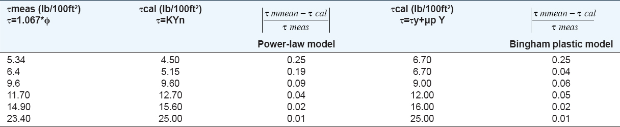
Table 4 shows the predicted stratigraphy and lithology description (field data). While Table 5 presents the well trajectory data which are shown in Figure 2.
Table 4. Predicted stratigraphy and lithology description (field data)
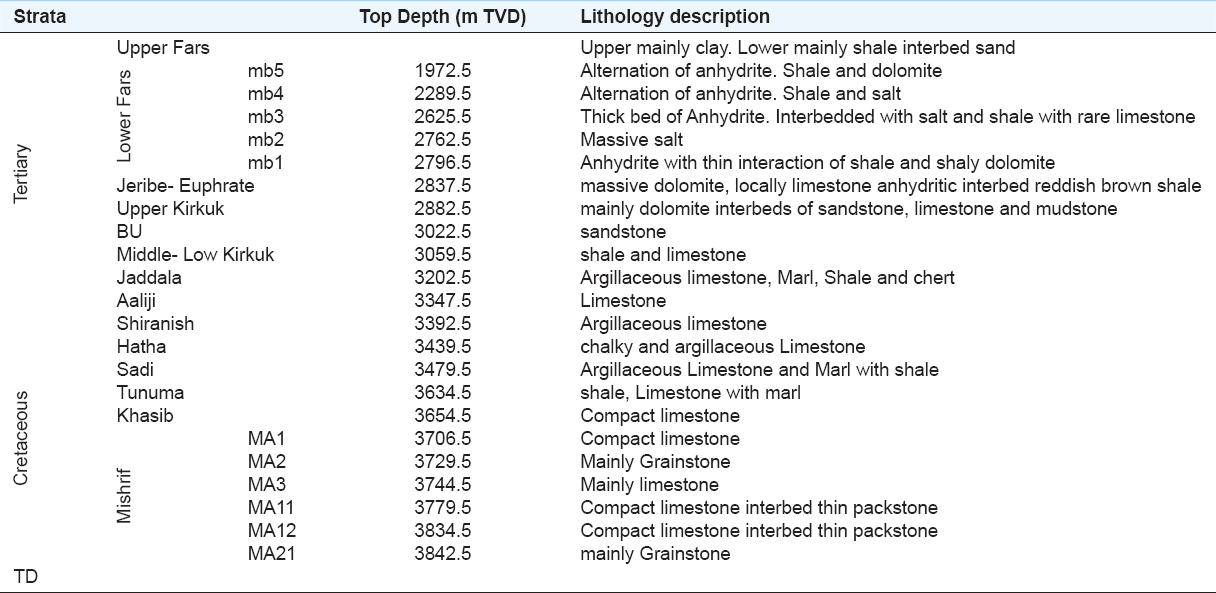
Table 5. Well trajectory data
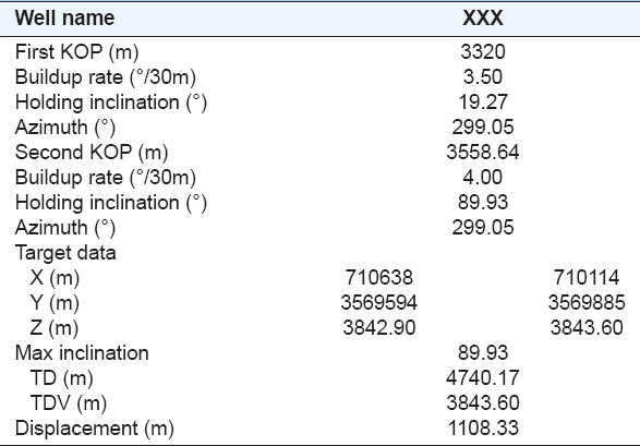
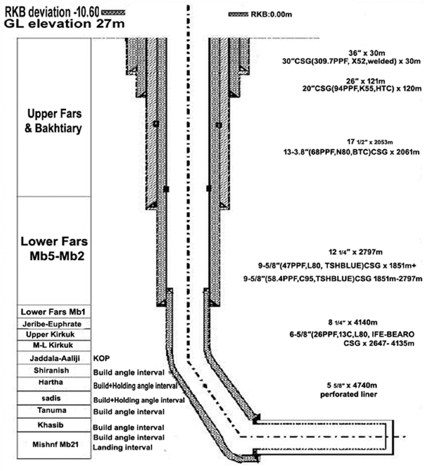
Figure 2. Schematic of the horizontal well
4. ANALYSIS AND DISCUSSION OF THE RESULTS
Table 6 shows the programmed fluid type and properties by intervals. Final results are presented in Table 7 along with Figure 3. From the results, the carrying is >0.5 for the chosen interval which means that cutting was transported to the surface efficiently. Furthermore, by calculating the annular velocity and slip velocity, the net cutting rise velocity was determined to give good of bit cutting movement to surface. Caring capacity is affected by mud weight and the result is the noticeable change in other parameters such as Yp of the fluid. High mud weight is necessary for controlling Yp, for example, in inches. Interval Yp was maintained at high level to reduce cuttings bed and bridge. The hole size has effect on flow rate as well when the hole size increases higher flow rate is needed for cleaning the well and that means more pumping is needed to reach the minimum annular velocity needed for hole cleaning. The mud tends to move faster in small hole size rather than in large holes from carrying capacity of cuttings and hole cleaning point of view. Hole cleaning is also affected by density of the cuttings. The increase in the cutting density leads to increasing the mud weight in the annulus, which in turn results in increasing the slip velocity of the cuttings. Any increase in slip velocity means that higher flow rate is required to accelerate the mud in the annulus for a better hole cleaning. For this reason, it is important to take the cuttings density in consideration.
Table 6. Programmed fluid type and properties by intervals
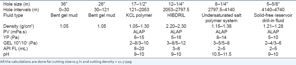
Table 7. Final results
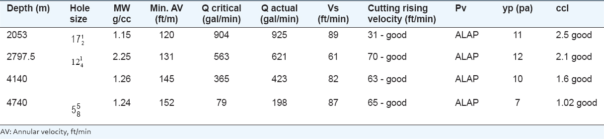
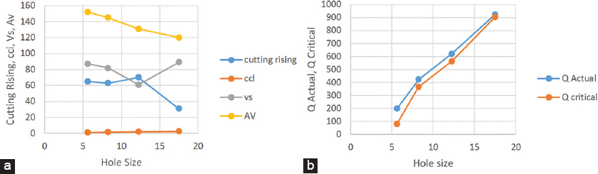
Figure 3. (a and b) Final results of cutting rising velocity and flow rates with hole size
Rate of penetration is also offering the cutting transporting that is by controlling the cuttings density in the wellbore. When there is low ROP that means the mud has more time to transport the cuttings due to the smaller slip velocity of cuttings, but it should be taken in consideration, lower ROP means the cost of drilling will increase due to larger time the operation will take.
The hole inclination is affecting the flow rate when the inclination of the hole increases that mean higher flow rates are needed. The need of higher flow rate will be too obvious when the well reduces 50º angle which means high pump efficiency is needed for this reason, but with cleaning the mud properties, it will be more capable to control the flow rate in specific range. Figures 4-9 show the relation of ECD and cutting transport ratio with measured depth for ROP = 10 m/h and different specific gravities of mud. Results of the graphs show that when MW = 2.30 g/cm3, different properties and flow rates, both ECD and cuttings transport ratio can meet the fluid demand and when MW 2.32 g/cm3, condition the properties as low as possible, recommend suitable flow rate for engineering. W equal MW and equal flow rate, viscous and get strength affect ECD more, with the same properties of the drilling mud, flow rate affects ECD more.
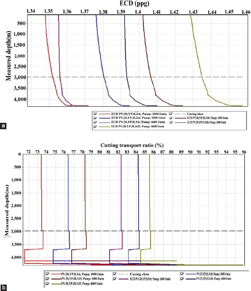
Figure 4. (a) ECD measured depth relationship, (b) cutting transport ratio and measured depth relationship for MW=1.36 gm/cm3
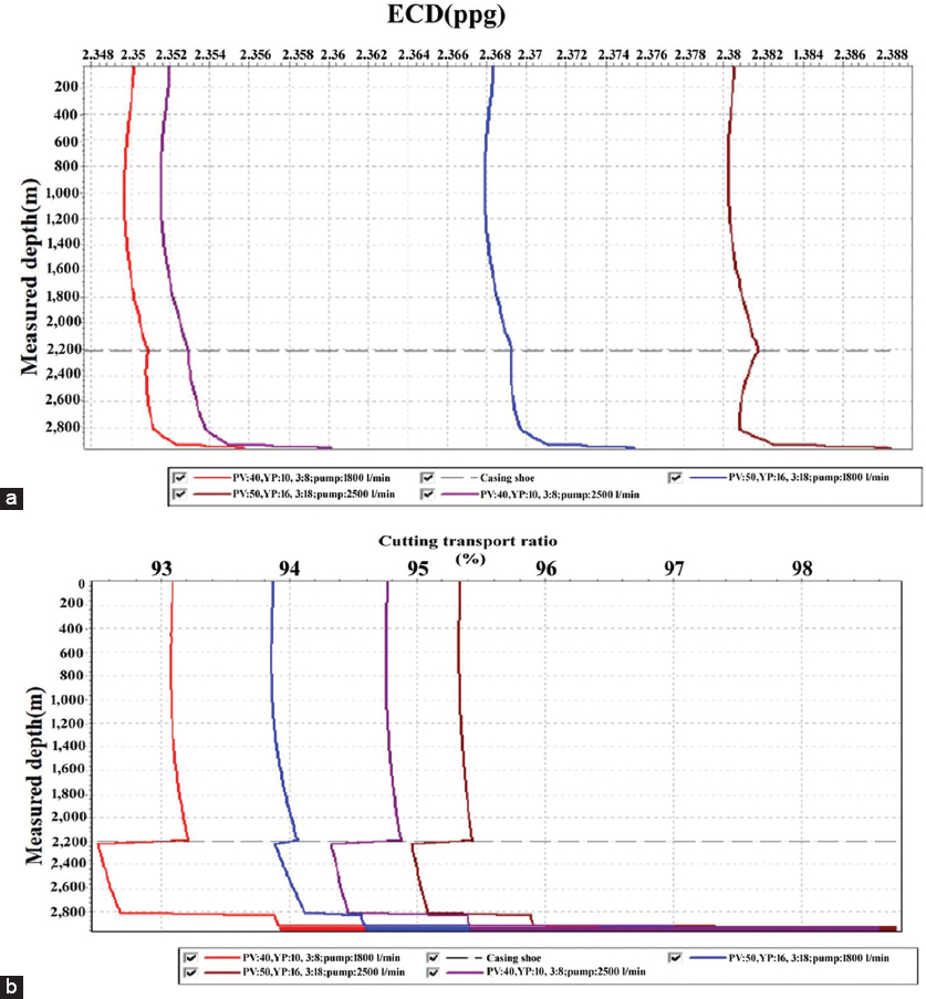
Figure 5. (a) ECD measured depth relationship, (b) cutting transport ratio and measured depth relationship for MW=2.32 gm/cm3
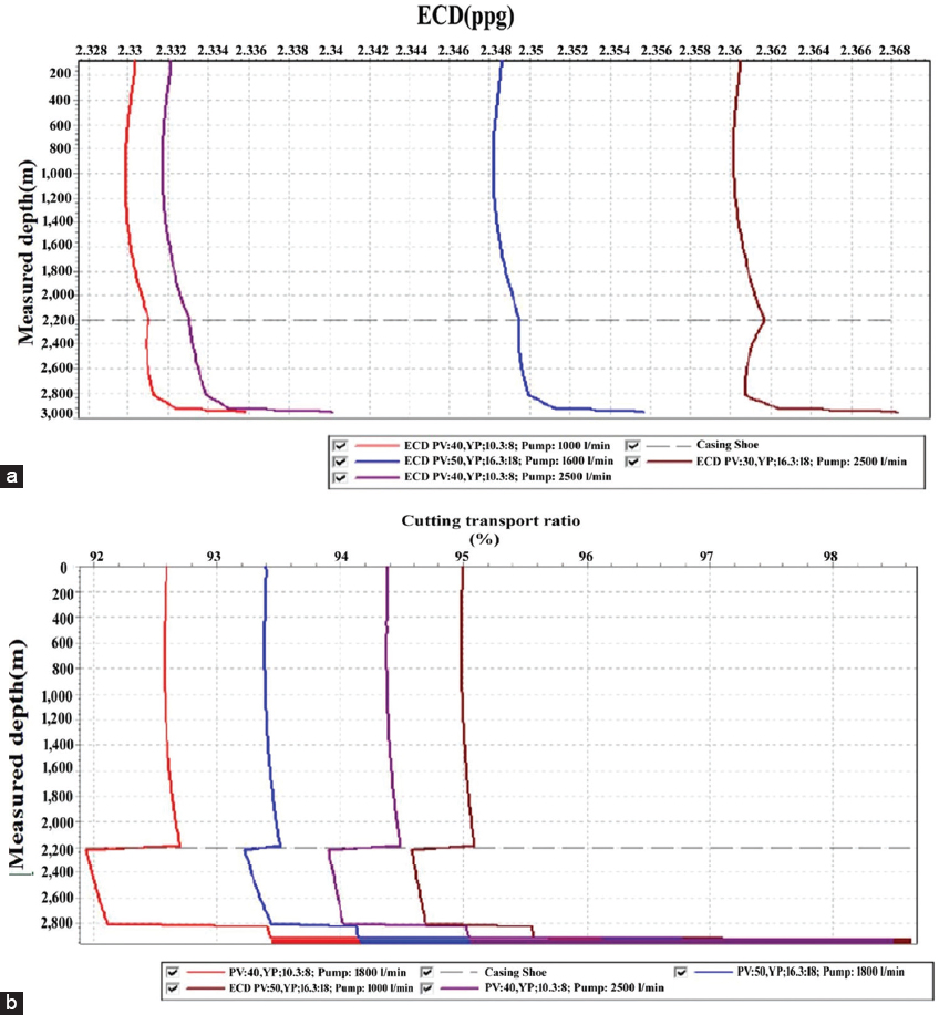
Figure 6. (a) ECD measured depth relationship, (b) cutting transport ratio and measured depth relationship for MW=2.30 gm/cm3
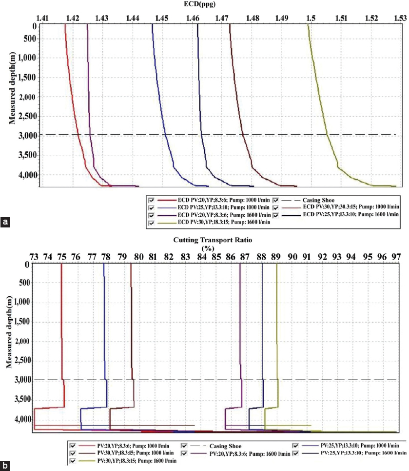
Figure 7. (a) ECD measured depth relationship, (b) cutting transport ratio and measured depth relationship for MW=1.35 gm/cm3
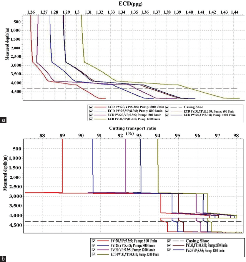
Figure 8. (a) ECD measured depth relationship, (b) cutting transport ratio and measured depth relationship for MW=1.21 gm/cm3
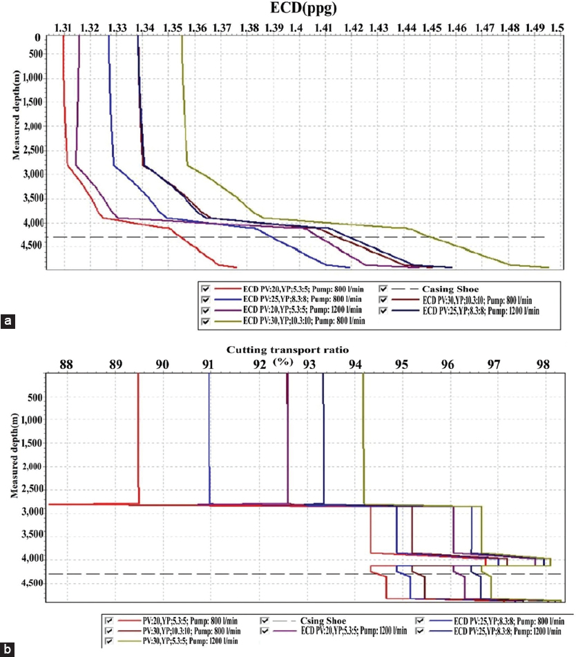
Figure 9. (a) ECD measured depth relationship, (b) cutting transport ratio and measured depth relationship for MW=1.26 gm/cm3
5. CONCLUSIONS
-
It was found that when MW = 2.30 g/cm3, different properties and flow rates, both ECD and cuttings transport ratio can meet the fluid demand and when MW 2.32 g/cm3, condition the properties as low as possible, recommend suitable flow rate for engineering.
-
With equal MW and equal flow rate, viscous and get strength affect ECD more, but with the same properties of the drilling mud, flow rate affects ECD more.
-
The flow velocity of the mud depends on the hole size; mudflow faster in small hole size than the case of larger hole size, this is valid for the carrying of cuttings and hole cleaning point of view.
-
Density of cuttings is a major factor that affects the hole cleaning efficiency, if there is an increase in density of cuttings; this leads to increase of mud weight in the annulus and eventually leads to increase in slip velocity of the cuttings.
-
It is essential to consider the cuttings density; this is for the purpose of mud acceleration on the annulus for good hole cleaning. The good hole cleaning requires high flow rate which occurs when slip velocity increases.
-
At low ROP, longer time needed for the cuttings to be transported due to lower slip velocity of the cuttings. Low ROP means higher drilling cost due to longer operational time.
-
Hole inclination is a major factor, increase in inclination requires a high flow rate, this becomes more obvious when the well reaches 50˚ and this will require a higher efficiency pump. In high inclined section, the flow should be turbulent to transfer the cuttings to the surface.
-
As the velocity of the cutting being raised increase, the carrying capacity index and hence the hole cleaning efficiency increase.
-
There is a direct proportional relationship between the slip velocity and the cutting density. Increasing the cutting density will lead to increase in slip velocity of the cuttings falling through the annulus down. However, while the cuttings diameter increases, slip velocity decreases, and hence, the annulus velocity should increase to clean the hole size to a higher extent.
6. RECOMMENDATIONS
It is recommended to do the following:
-
A study work on the cleaning efficiency on horizontal wells
-
Research study on the effect of hole cleaning during the underbalanced drilling
-
Study the role of hole cleaning in high pressure/high temperature of high inclined wells.
7. NOMENCLATURE
-
• AV - Annular velocity, ft/min.
-
• CCa - Coefficient for the annulus of drilling collars.
-
• COB - Coefficient through inside of drill collars.
-
• CSe - Surface coefficient.
-
• Cpa - Coefficient for the annulus of pipe.
-
• Cpb - Coefficient through inside of pipe and tool joint
-
• Denp - Cutting density, ppg.
-
• Dh - Diameter of wellbore, in.
-
• Do - Outside diameter of tubular, in.
-
• Dp - Diameter of drill pipe, in.
-
• ECD - Equivalent circulating density, Ib/gal.
-
• K - Power-law constant (power law)
-
• Lc - Drill collar length, ft.
-
• Lp - Drill pipe length, ft
-
• n- Flow behavior index (power law)
-
• Ps - Surface pressure, ft.
-
• Pv - Plastic viscosity, cp
-
• Q - Flow rate, gpm.
-
• Rea - Reynolds number in annulus.
-
• Vc - Critical velocity ft/sec
-
• Vf - Viscosity correction factor.
-
• Vs - Slip velocity, ft/sec
-
• W - Mud weight, ppg
-
• τ - Shear stress, Ib/100ft2
-
• ɣ - Shear rate, sec−1.
REFERENCES
Akram, H. & Maha, R. H. (2017). Drilling optimization of a selected field in Kurdistan region. UKH Journal of science and Engineering, 1, 39-52.
Aswad, Z. A. R. (1996). New approach for selecting the best non-Newtonian rheological model. Polymer Plastics Technology and Engineering Journal, 35(2), 233-241.
Bourgoyne, A. & Millhein, K. (1991). SPE text book series. Applied Drilling Engineering. Vol. 2. Texas: SPE Richarson.
Ciuo, B. & Liu, G. (2011). Applied Drilling Circulation System; Hydraulic, Calculations and Models. Oxford: Gulf Professional Publishing.
Duan, M., Miska, S. & Yu, M. (2010). Transport of Small Cuttings in Extended Reach Drilling. USA: University of Tusla.
Rabia, H. (1998). Oil Well Drilling Engineering Principles and Practice. Gaithersburg, MD, USA: Graham and Trotman.